Introduction
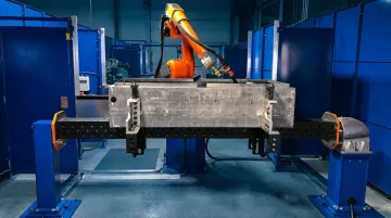
Buying a robot arm is the easy part. Actually integrating it into a reliable production cell — one that welds consistently, communicates correctly, and passes quality validation — is where most projects encounter serious problems.
According to KC Robotics, most robotic welding failures trace back to part variation, poor fixturing, and unclear requirements rather than robot hardware defects. The equipment rarely fails first. Planning does.
Successful robotic welding integration requires coordination across five distinct areas:
- Welding process expertise
- Cell design and fixturing
- Robot programming
- Infrastructure and utilities
- Quality validation
A gap in any one of these areas produces defects, rework, or safety failures — most of which cost far more to fix post-installation than to prevent upfront.
This guide covers the complete integration process — from site readiness checks through post-installation validation — giving engineers and plant managers what they need to know before, during, and after deployment.
Key Takeaways
- Robotic welding integration is a multi-phase engineering process, not an off-the-shelf purchase
- Infrastructure, fixturing, and part suitability must be confirmed before equipment is ordered
- Integration follows a defined sequence: site prep → cell layout → system connection → programming → validation
- Skipping post-integration validation is a costly mistake — it's also the most preventable
- For aerospace, defense, or high-tolerance applications, engaging a certified partner early cuts rework, certification delays, and compliance failures
Your Guide to Robotic Welding Integration
Robotic welding integration broadly involves four phases: preparation, physical cell setup, system connection and programming, and validation. Hirebotics notes that traditional integration typically takes several months from decision to production — not weeks. Complex applications with tight tolerances or high part variety take longer.
The coordination required is real. Robot OEMs or integrators, welding power source suppliers, fixture fabricators, programmers, and the customer's production team all need to align on requirements before a single piece of equipment ships.
Prerequisites and Site Readiness
Infrastructure must be confirmed before integration begins — not during it. Required site conditions include:
- Electrical supply: Three-phase power for welding power sources and robot controllers. Lincoln's Power Wave R450, for example, draws up to 80A at 40% duty cycle on a 208V supply — verify your service capacity by duty cycle, not just voltage
- Floor space: Adequate footprint for the robot cell, safety fencing, and operator access paths
- Compressed air: Required if the system uses pneumatic fixtures or torch cleaning stations
- Ventilation/fume extraction: Required for all arc welding processes — address this in the facility plan, not retrofitted later
Part suitability is the most critical go/no-go check before any equipment is ordered. Robots require geometrically consistent, repeatable parts — excessive fit-up variation means the robot's fixed path will produce inconsistent welds. No amount of programming fixes a fixturing or part quality problem. Map fit-up tolerance stackup by joint family before integration begins.
Communication protocol compatibility also requires early attention. Verified fieldbus options include EtherNet/IP, DeviceNet, Profibus, Profinet, and Modbus-TCP — the right choice depends on your brand combination. Lincoln's Power Wave R450 uses ArcLink and interfaces directly with FANUC, Yaskawa, ABB, and KUKA robots; Miller's Auto-Continuum series supports EtherNet/IP and DeviceNet. Confirm compatibility before equipment ships, not after.
Do not proceed if:
- Fixturing hasn't been designed and validated
- Weld joint accessibility hasn't been confirmed for the robot geometry
- The welding process (MIG, TIG, spot) hasn't been matched to the material and application
For aerospace and defense applications, traceability and documentation requirements — AS9100D, AWS D1.1 — must be designed into the cell from day one. Retrofitting compliance requirements into an already-installed cell is expensive and often incomplete. DM&E operates under AS9100D certification with AWS-certified welders, which means these requirements are addressed at the design stage, not during final sign-off.
Key Equipment and Components
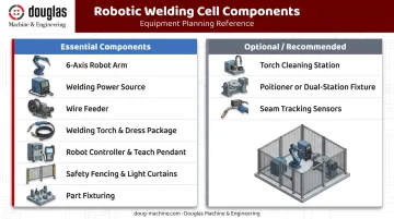
A complete robotic welding cell includes more than the robot arm. Core components:
| Component | Essential / Optional |
|---|---|
| 6-axis articulated robot arm | Essential |
| Welding power source | Essential |
| Wire feeder (MIG/MAG) | Essential for MIG/MAG |
| Welding torch and dress package | Essential |
| Robot controller and teach pendant | Essential |
| Safety fencing and light curtains | Essential |
| Part fixturing | Essential |
| Torch cleaning/anti-spatter station | Strongly recommended |
| Positioner or dual-station fixture | Optional — improves throughput on larger/asymmetric parts |
| Seam tracking sensors | Optional — important when joint geometry varies |
Internal cable dress packages deserve attention. ABB's integrated dressing on the IRB 1520ID routes welding power, wire, shielding gas, and air internally through the arm, extending hose life by 50% and reducing interference in tight-fixture environments. For high-duty-cycle cells, this pays off quickly in reduced maintenance.
When mixing robot brands with third-party power sources, verify whether interface kits or middleware are required. This is a prerequisite-phase question — the answer affects both timeline and budget before a purchase order is placed.
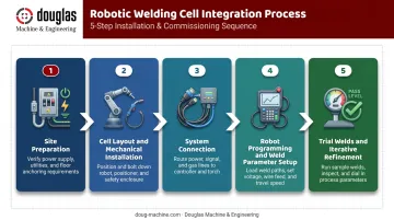
How to Integrate a Robotic Welding System: Step-by-Step
Step 1 — Site preparation Confirm all infrastructure is in place before any equipment moves in:
- Power supply verified at rated duty cycle
- Ventilation system active and tested
- Floor anchoring points marked
- Cable routing path planned and cleared
Establish the safety perimeter and mark out the full cell footprint first.
Step 2 — Cell layout and mechanical installation Position and anchor the robot base. Install positioner or fixture table. Route dress-out cables — internal cable packages reduce wear and improve path accuracy compared to external dressing. Mount the welding torch to the robot wrist and confirm clearances at all programmed positions.
Step 3 — System connection Wire the robot controller to the welding power source using the confirmed interface protocol. Connect the wire feeder and establish communication with auxiliary devices — torch cleaner, arc sensors, seam tracker if fitted.
Before powering on, verify every E-stop circuit and safety interlock is active. Skipping this check creates risk that no amount of programming skill can fix downstream.
Step 4 — Robot programming and weld parameter setup Teach weld paths using the pendant or offline programming software. Set parameters — voltage, wire feed speed, travel speed, shielding gas flow rate — based on material type and joint geometry.
AWS-certified welders who understand robotic systems bring process knowledge that motion programmers alone cannot replicate. Bead profile behavior, heat input effects, and parameter interaction all shape final weld quality in ways that only hands-on welding experience reveals. Test all programs at reduced speed before running at full cycle rate.
Step 5 — Trial welds and iterative refinement Run test welds on representative parts. Inspect visually and dimensionally. Adjust TCP (tool center point) calibration, path timing, and weld parameters as needed. Do not approve programs for production until welds consistently meet acceptance criteria across multiple parts.
Post-Integration Checks and Validation
A correctly integrated robotic welding cell shows:
- Consistent bead profile and fusion across all parts in the run
- Repeatable cycle times with no arc-starting failures or wire feed jams
- Safety interlocks functioning correctly at every test
- Dimensional compliance on welded assemblies
Validation methods should match application requirements:
- Visual inspection against defined acceptance criteria (minimum for all applications)
- Dimensional checks on welded assemblies
- Destructive testing (bend tests, macro sections) where required by the specification
- NDT (non-destructive testing) (radiographic, ultrasonic, or dye-penetrant inspection) for aerospace, pressure, or structural applications
Regulated industries carry the strictest documentation requirements. For aerospace and defense customers, DM&E's quality framework includes First Article Inspection reporting to AS9102 standards, CMM analysis, and dimensional verification on certified granite tables — supporting the complete documentation trail that regulated programs require.
Skipping or compressing validation to hit a production start date is the most predictable cause of expensive post-ramp failures. Weld defects discovered in field-assembled products cost several times more to address than defects caught during cell commissioning.
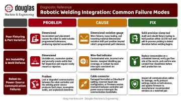
Common Robotic Welding Integration Problems and How to Fix Them
Most integration issues fall into predictable categories. Recognizing the pattern quickly shortens root-cause diagnosis.
Poor Fixturing and Part Variation
Problem: Welds are inconsistent, or the robot repeatedly fails to find the joint.
Cause: Fixture locating tolerances are too loose, allowing parts to shift between cycles. Incoming part variation may also exceed what the robot's fixed path can accommodate.
Fix: Tighten fixture locating tolerances. If incoming part variation is unavoidable, add seam tracking — options like FANUC's Through Arc Seam Tracking (TAST) or Lincoln Electric laser vision systems provide real-time path correction. Robot programming alone cannot compensate for a fixturing problem.
Arc Instability and Weld Defects
Problem: Welds show porosity, undercut, inconsistent penetration, or frequent arc outages.
Cause: Incorrect weld parameters for the material and joint, contaminated base metal, shielding gas flow issues, or worn contact tips and liners.
Fix:
- Verify shielding gas coverage and flow rate at the torch
- Inspect and replace consumables on a defined schedule — don't wait until degradation is visible
- Review weld parameters against material specifications and joint geometry
- Confirm base metal cleanliness and consistency across incoming stock
Robot-to-Power-Source Communication Failures
Problem: The robot triggers a weld but the power source doesn't respond, or arc data isn't being logged.
Cause: Incorrect interface configuration, incompatible communication protocols, or a wiring fault in the interface cable.
Fix:
- Confirm the interface type is correctly configured in both the robot controller and the power source
- Check all cable terminations for faults or loose connections
- Consult both OEMs' integration documentation before assuming compatibility
- Brand combinations that worked in prior installations don't guarantee compatibility in a new configuration — always verify explicitly against the current setup
Pro Tips for Successful Robotic Welding Integration
Involve experienced welders in programming. The best robot programs come from people who understand weld metallurgy — not just motion control. AWS-certified welders grasp how voltage, travel speed, and wire feed interact to produce the bead profile a joint requires. That process knowledge belongs in the program from the start.
Start with high-volume, geometrically consistent parts. Your first integration is partly a learning exercise. Choose parts where ROI is clear and joint geometry is forgiving — not your most complex assemblies.
Document everything from day one. Weld parameter records, TCP calibration data, program versions, and validation sign-offs should be captured systematically. For aerospace and defense programs this is mandatory, but even for industrial work it dramatically simplifies troubleshooting when issues appear six months into production.
Train operators before go-live. Production staff need to recognize when the cell is running incorrectly, respond to faults appropriately, and know when to escalate versus attempt a local fix. Undertrained operators are a leading cause of defects slipping through after an otherwise successful integration.
Conclusion
Robotic welding integration is an engineered system. The quality, consistency, and longevity of the cell depend directly on how carefully each phase — prerequisites, cell setup, programming, validation — was executed. A cell that clears commissioning on a compressed timeline often surfaces problems within the first production quarter.
For complex or regulated applications, engaging a certified manufacturing partner early consistently outperforms fragmented project management. DM&E manages design, fabrication, integration, and quality sign-off as a single accountable partner — which means handoff gaps don't become late-stage failures.
Heat treatment and plating are coordinated through qualified external partners where needed, but core integration responsibility stays in one place.
That single point of accountability matters most at the start. If you're planning a robotic welding integration for aerospace, defense, or precision industrial applications, contact DM&E before equipment is specified — not after it's already on the floor.
Frequently Asked Questions
How much does a welding robot cost?
Turnkey robotic welding cells typically range from $50,000 to over $200,000, according to KC Robotics, depending on robot reach, power source capability, fixture complexity, and programming scope. The robot arm itself is only part of the total — fixturing, safety guarding, software, and installation add substantially to the investment.
Is robotic welding worth it?
For high-volume, geometrically consistent parts, yes — robotic welding delivers consistent quality, higher throughput, and reduced labor cost. KC Robotics reports payback periods of 8–18 months for well-matched applications, though low-volume, high-mix production with frequent changeovers erodes the productivity benefit.
What industries use robotic welding?
Primary industries include automotive, aerospace and defense, heavy equipment, agricultural machinery, construction, and industrial fabrication. The shared thread: repetitive joint geometries, sufficient part volume, and consistent fit-up tolerances.
What are the different types of welding robots?
The three most common configurations are:
- 6-axis articulated robots — highest flexibility for complex joint geometries
- Collaborative robots (cobots) — lower payloads, easier to redeploy in high-mix environments
- Gantry and rail-mounted systems — extended reach for large-format structural parts
Are there robotic TIG welders?
Yes — robotic TIG welding is used for high-precision applications on stainless steel, aluminum, and exotic alloys. It's more difficult to automate than MIG/MAG because it requires tighter joint fit-up, precise arc length control, and careful management of high-frequency arc starts, which can interfere with nearby electronics.